Difference between revisions of "SPN"
m (→Elements) |
|||
| (4 intermediate revisions by the same user not shown) | |||
| Line 39: | Line 39: | ||
{{Vspace}} | {{Vspace}} | ||
| − | |||
| − | |||
| − | |||
<table cellpadding="10"> | <table cellpadding="10"> | ||
| Line 59: | Line 56: | ||
<td align="center" style="border-bottom:solid 1px #999999;">'''Data'''</td> | <td align="center" style="border-bottom:solid 1px #999999;">'''Data'''</td> | ||
<td style="border-bottom:solid 1px #999999;"> | <td style="border-bottom:solid 1px #999999;"> | ||
| − | Any data item that is produced by the | + | Any data item that is consumed or produced by an activity / procedure in the workflow. Typically this may be a file, but it can also be a stream, a series of files, an object in memory, or one or more tables in a datamodel. The nature of the data is clarified in the description. Labels are short mnemonics. Examples: ID, Tor, s3D, mapX. Data items have one incoming relationship line (a data item is produced by exactly one activity) and can have more than one outgoing relationships (data items can be used by more than one activity). The data icon can be used to mark the ''Begin'' and ''End'' state for the process. ''Begin'' icons are not produced by an activity. |
</td> | </td> | ||
</tr> | </tr> | ||
| Line 151: | Line 148: | ||
<tr> | <tr> | ||
<td style="border-bottom:solid 1px #999999;">[[File:SPN_Note.png|100px]]</td> | <td style="border-bottom:solid 1px #999999;">[[File:SPN_Note.png|100px]]</td> | ||
| − | <td align="center" style="border-bottom:solid 1px #999999;">''' | + | <td align="center" style="border-bottom:solid 1px #999999;">'''Note'''</td> |
<td style="border-bottom:solid 1px #999999;"> | <td style="border-bottom:solid 1px #999999;"> | ||
A Note contains a comment about a component of the diagram or about its functions or purpose. The sense of the arrow always goes against the dataflow to avoid confusing a note with an activity. Short information is contained in the Note, longer information is annotated at the side and referenced to the Note with a label. | A Note contains a comment about a component of the diagram or about its functions or purpose. The sense of the arrow always goes against the dataflow to avoid confusing a note with an activity. Short information is contained in the Note, longer information is annotated at the side and referenced to the Note with a label. | ||
| Line 180: | Line 177: | ||
</table> | </table> | ||
| + | |||
| + | {{Vspace}} | ||
| + | |||
| + | =="Rules"== | ||
| + | |||
| + | {{Vspace}} | ||
| + | |||
| + | ;I - Be clear and explicit | ||
| + | :This is "Rule Number One". As a corollary, any other rule or convention can be suspended if this helps the clarity of the diagram or improves the message. | ||
| + | |||
| + | ;II - Name, reference, version | ||
| + | :A name for the process is listed on the top left of the diagram. A reference is on the top right, it is used in other documentation and to identify nested diagrams. A textual summary may appear at the top. Diagrams and references must be versioned. | ||
| + | |||
| + | ;III - Begin and End states | ||
| + | :Abstract Begin and End states of a process are not normally drawn since they should be obvious from the context. An activity can be started with an input parameter or data element, and ends with an output data element. | ||
| + | |||
| + | ;IV - Connecting arrows | ||
| + | :Connecting arrows are drawn as horizontal/vertical lines, never oblique lines. Crossing lines are avoided if possible. Arrows should not move against the dataflow. | ||
| + | |||
| + | ;V -Multiple data items, multiple resources | ||
| + | :If multiple data elements are produced as output or used as input, they are connected to their respective source or target element with distinct lines, unless there are more than three. If there are more than three connections, they are merged into a connector element which is attached to an activity through a single line. | ||
| + | |||
| + | :If multiple instances of syntactically and semantically equivalent data items are produced, this is indicated with a multi data icon. These are connected to the activity that produces them with a single line. | ||
| + | |||
| + | :If the multiple elements are connected to an activity, this indicates that are processed sequentially. Parallel processing is indicated through braces. | ||
| + | |||
| + | :If the multiple elements are merged in an activity, this is indicated with a brace. | ||
| + | |||
| + | ;VI - Nesting | ||
| + | :A procedure can be detailed at higher resolution on a separate sheet. All input and output must be shown at the parent level. This ensures that the expanded view of a procedure introduces no reference to streams or processes that were not present in the parent view and thus ensures that descriptions are locally complete. Nested diagrams are indicated with a box and annotated with a reference/version. The containing page is referenced like a continuation diagram. | ||
| + | |||
| + | ;VII - Continuation | ||
| + | :If a process needs to be split accross several pages or diagrams, all output data items have connecting arrows that end at the bottom of the page on a pale, dotted line, and their icons are repeated at the top of the next page. The continuing page is referenced. | ||
| + | |||
| + | ;VIII - Color | ||
| + | :All elements that are part of the process are drawn with black lines, all elements that provide additional structure or annotation are drawn grey or in a pale colour. Icons are filled with a light colour to visually offset them clearly from the page. Colours may be used to visually group functionally related elements. | ||
| + | |||
{{Vspace}} | {{Vspace}} | ||
Latest revision as of 13:06, 4 February 2016
SPN
Structured Process Notation
SPN (Structured Process Notation) is a lightweight, expressive notation for the design of dataflow diagrams.
Contents
Introduction
Engineering workflow-centric software for research laboratories requires transparent, high level models to structure the design and to document the overall organisation of the code. However current methodologies are not well suited for this task, focussing on the implementation of objects rather than on the integration of functions and suffering from poor information design principles. SPN (Structured Process Notation) is an intuitive, lightweight alternative loosely based on SADT / IDEF0. SPN is intuitive by consistently applying a directional metaphor that is close to implementation, expressive by using icons and avoiding any superfluous elements, simple by minimizing the number of symbols and using explicit annotations, granular by supporting multiple levels of detail through nesting, and extensible.
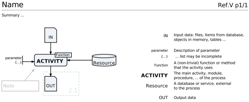
The core SPN elements and their general layout. Icons are drawn on the left of the page, labels and descriptions on the right. Fonts may be formatted to emphasize correspondence. Input data enters an activity from the top, parameters from the left, database, libraries, services, repositories and similar resources from the right and output data leaves the activity at the bottom. Connections are drawn with black lines and all other lines in the diagram are not black to make them visually distinct. An activity can be annotated with functions, methods or algorithms. Notes and comments can be added for clarification, they are formatted in grey, the sense of their pointing arrows is always against the dataflow and these arrows are not connected to icons, to avoid confusion. A pale dotted line groups elements that are described in greater detail elsewhere, a reference is included. All elements of the diagram are optional. A Name for the process and a versioned reference ID (process prefix, number, version, page). The page number is optional for a single-page diagram. A summary at the top may be useful.
Features include:
- A structured, spatial organization of components intuitively depicts data flow.
- Information is not implicit in a complex grammar of symbols but made explicit; the set of symbols that are used is small and they are iconic, i.e. their shape is related to their semantics.
- SPN's process-centric view of data flow is close to implementation.
- Icons are separated from text to allow uncluttered spatial representation of relationships, but explicit descriptions are available on the diagram by placing elements and descriptions at corresponding heights on the diagram and relating them through mnemonic labels.
- Nesting of diagrams is encouraged. Expanding procedures at a higher level of granularity into more detail in a separate diagram structures the components of the workflow without overloading individual diagrams with too much detail.
Elements
"Rules"
- I - Be clear and explicit
- This is "Rule Number One". As a corollary, any other rule or convention can be suspended if this helps the clarity of the diagram or improves the message.
- II - Name, reference, version
- A name for the process is listed on the top left of the diagram. A reference is on the top right, it is used in other documentation and to identify nested diagrams. A textual summary may appear at the top. Diagrams and references must be versioned.
- III - Begin and End states
- Abstract Begin and End states of a process are not normally drawn since they should be obvious from the context. An activity can be started with an input parameter or data element, and ends with an output data element.
- IV - Connecting arrows
- Connecting arrows are drawn as horizontal/vertical lines, never oblique lines. Crossing lines are avoided if possible. Arrows should not move against the dataflow.
- V -Multiple data items, multiple resources
- If multiple data elements are produced as output or used as input, they are connected to their respective source or target element with distinct lines, unless there are more than three. If there are more than three connections, they are merged into a connector element which is attached to an activity through a single line.
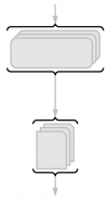
- If multiple instances of syntactically and semantically equivalent data items are produced, this is indicated with a multi data icon. These are connected to the activity that produces them with a single line.
- If the multiple elements are connected to an activity, this indicates that are processed sequentially. Parallel processing is indicated through braces.
- If the multiple elements are merged in an activity, this is indicated with a brace.
- VI - Nesting
- A procedure can be detailed at higher resolution on a separate sheet. All input and output must be shown at the parent level. This ensures that the expanded view of a procedure introduces no reference to streams or processes that were not present in the parent view and thus ensures that descriptions are locally complete. Nested diagrams are indicated with a box and annotated with a reference/version. The containing page is referenced like a continuation diagram.
- VII - Continuation
- If a process needs to be split accross several pages or diagrams, all output data items have connecting arrows that end at the bottom of the page on a pale, dotted line, and their icons are repeated at the top of the next page. The continuing page is referenced.
- VIII - Color
- All elements that are part of the process are drawn with black lines, all elements that provide additional structure or annotation are drawn grey or in a pale colour. Icons are filled with a light colour to visually offset them clearly from the page. Colours may be used to visually group functionally related elements.
In Practice
I start drawing sketches by hand on a blackboard, or whiteboard to get a first overview and quickly move things around, reconnect and rearrange. A final, handdrawn sketch is fine, if an electronic diagram is required, I find after experimenting with many alternatives that Google Slides is currently the best tool to develop SPN diagrams. Here is a link to a SPN template that you can copy and use for your own diagrams.
| Best Practice in SPN Diagrams | |
| Labels | |
| Good |
|
| Bad |
|
| Worst |
|
| Connectors | |
| Good |
|
| Bad |
|
| Worst |
|
| Color | |
| Good |
|
| Bad |
|
| Worst |
|
| Even Worse than Worst |
|
Example
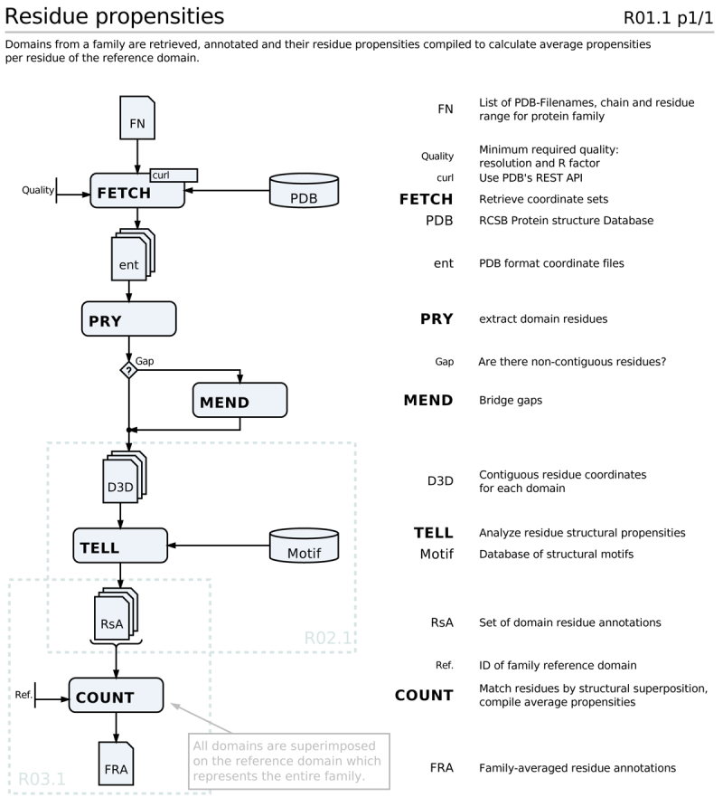
A sample process. Note that FETCH generates multiple files, PRY/MEND and TELL operate on these files sequentially. The files are merged by COUNT, which produces a single output list. Two nested diagrams for TELL and COUNT are referenced, there is no off-page continuation, the process terminates with FRA.
Further reading and resources
- A template of SPN icons and sample workflows using Google Slides
- Wikipedia article on SADT
- Wikipedia article on IDEF0 IDEF0, a successor to SADT.


